The importance of remaining updated in your field of expertise.

I have just taken part in a one-hour webinar. The topic of the webinar was one I thought I knew everything about.

As the webinar continued, I learned that I was very well versed in the topic, and I even got all the polls that they had right. The speaker was brilliant, well prepared and on top of his game.

Towards the end of the webinar it came to light that some standards had recently been updated, and I realised that I had not aware of this. The result is that with the changes in the standards new requirements had been identified. This experience has just reiterated the importance of staying on top of your game to me.

To remain relevant in the 21st century we must constantly study. This includes studying further in our field at a college, Technicon, or university, reading articles relevant to your industry and/or job, attending webinars, attending courses, etc. Failing to do so will result in you becoming obsolete and irrelevant.

Training for July 2020

We are happy to report that we are able to start training after Government relaxed the restrictions on conferences. Please note that we will comply with the conditions as set out by government:

  1. Temperature of every attendee will be measured and recorded.
  2. Sanitizing.
  3. Social distancing.

Book now to secure you space

JHB_CT July & Aug 2020.jpg

July_Aug 2020.jpg

All Regions July 2020

Don’t delay, contact us NOW to make a booking

Info Business Card 2020

Transmitting Video of Twisted Pair Cabling

Game-changing HDBaseT and SDVoE ease your AV deployments…

Content Dam Cim Native Articles 2019 05 Avoverip Thumbnail

Siemon1 Fig1

While the term video over Internet Protocol (IP) has existed for quite some time, it essentially has been used to refer to any type of Internet-based video transmission. However, regardless of the cabling medium, most of these systems to date have been supported by traditional audiovisual (AV) architectures where signals are sent and received via AV transmitters, receivers and video matrix switches rather than using true Ethernet LAN switches. This has prohibited AV transmission from truly converging onto existing network cabling infrastructures, and they have instead remained on their own standalone network. But all that is changing with AV over IP that uses standard network equipment to transmit and switch AV signals.

HDBaseT: The 5Play Game Changer

Over the past decade, balanced twisted-pair copper cabling (i.e., Category 6 and Category 6A) has become an AV-supporting medium using baluns that enable composite and analog video to extend over the twisted-pair cabling. The use of AV over twisted-pair cabling really came to fruition in 2010 with the introduction of the HDBaseT standard.

Since it was introduced by the HDBaseT Alliance, HDBaseT has evolved to support what has been dubbed “5Play”—the transmission of ultra-high definition 4K video and audio along with 100 Mb/s Ethernet (100Base-T), USB, bidirectional control signals and 100W of power (power over HDBaseT) over a single twisted-pair cable to 100 meters using standard 8P8C (RJ45) connectivity.

While HDBaseT can run over Category 5e (to limited distances) and Category 6 cabling, the HDBaseT Alliance and HDBaseT equipment vendors all recommend the use of Category 6A twisted-pair unshielded cabling at a minimum to support the bandwidth required for 4K signals and reach the full 100-meter distance. Many AV vendors recommend stepping that up to Category 6A or Category 7A shielded twisted-pair cable to ensure a truly robust performance—especially for installations with unmanaged environmental factors. Shielded Category 6A or Category 7A offers better resistance to alien crosstalk, which has a significant impact on HDBaseT signals wherever multiple cable are bundled together. Further, with power over HDBaseT (POH) running at higher levels of 100 Watts, shielded cabling offers far superior heat dissipation and thermal stability.

While HDBaseT remains the most popular AV protocol over twisted-pair cabling and is at least a step towards using a common cabling medium, it is not true IP as it used a different packetization protocol (T-packets). Further, an HDBaseT system must use HDBaseT equipment, so it essentially must remain as a standalone system and therefore does not meet the true definition of IP convergence.

SDVoE: The Ethernet Solution

Today, there are newer AV protocols that truly can be considered an IP system because they transmit AV signals over standard off-the-shelf Ethernet LAN switches. Introduced in 2017, Software Defined Video over Ethernet (SDVoE) that supports uncompressed 4K video, audio, control and 1 Gb/s Ethernet is one such platform that aims to offer greater saving, flexibility and scalability compared to HDBaseT since it addresses the full 7-layer OSI model and leverages what we in the IT industry already use for transmitting data—standards-based network cabling, Ethernet, TCP/IP and low-latency switching. Plus, it eliminates the use of AV video matrix switches, which typically cost about 90% more per port than a standard Ethernet switch since Ethernet ports are bidirectional and can therefore be used as both an AV input and output port. Ethernet switches also typically take up about a quarter of the rack unit space compared to a video matrix switch, and they support power over Ethernet (PoE) capable of delivering up to 90 Watts of power.

While a few other AV over IP protocols have been introduced, such as the Society of Motion Picture and Television Engineers SMPTE 2110 standard that defines the uncompressed transmission of HD video over IP, JPEG-2000 lightly compressed video over IP, and high-efficiency H.264 and H.265 video compression for video over IP, most industry professionals see SDVoE and the most disruptive technology and the one that truly paves the way for fully converged AV over IP. In response, the HDBaseT Alliance introduced HDBaseT over IP shortly after the introduction of SDVoE to also leverage standards-based network infrastructures and 10 Gb/s Ethernet switches for cross-campus transmission, but it requires HDBaseT-to-HDBaseT-IP bridges and HDBaseT-IP switches.

When it comes to SDVoE, it’s not just that Category 6A cabling is recommended—it’s required. SDVoE requires a 10 Gb/s Ethernet network (10GBASE-T), which can only be supported by a minimum of Category 6A cable. And for the same reasons as HDBaseT, shielded cabling is recommended—eliminating crosstalk and providing superior heat dissipation and thermal stability for remote powering (PoE in the case of SDVoE).

Prepare Your AV Cabling System

Regardless of whether your AV system is HDBaseT or a true IP solution like SDVoE, you need to ensure you have the right cabling system to support it — one with superior performance to fully combat video disrupting alien crosstalk for a clearer picture. In addition, selecting shielded twisted-pair cabling with a higher operating temperature of 75°C will ensure better heat dissipation to support the higher power levels of POH and PoE (100 and 90 Watts) needed to power video displays.

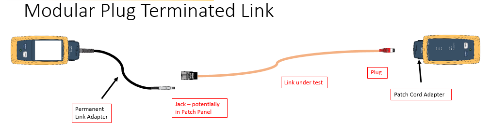
To avoid the use and expense of unsightly outlets and patch cords, digital displays can be connected directly to the cabling infrastructure using field-terminated plugs and a standards-based MTPL configuration.

Reference: https://www.cablinginstall.com/sponsored/siemon-company/article/16482565/av-over-twistedpair?cmpid=&utm_source=enl&utm_medium=email&utm_campaign=cim_data_center_newsletter&utm_content=2019-06-10&o_eid=0218E2673490H7U&rdx.ident%5Bpull%5D=omeda%7C0218E2673490H7U

Passive Optical Networks (PONs)

A passive optical network (PON) is a system that brings optical fibre cabling and signals all or most of the way to the end user. Depending on where the PON terminates, the system can be described as fiber-to-the-curb (FTTC), fiber-to-the-building (FTTB), or fibre-to-the-home (FTTH).

A PON consists of an Optical Line Termination (OLT) at the communication company’s office and a number of Optical Network Terminals (ONTs) near end users. Typically, up to 64 ONTs can be connected to an OLT. The passive simply describes the fact that optical transmission has no power requirements or active electronic parts once the signal is going through the network.

All PON systems essentially have the same theoretical capacity at the optical level. The limits on upstream and downstream bandwidth are set by the electrical overlay, the protocol used to allocate the capacity and manage the connection. The first PON systems that achieved significant commercial deployment had an electrical layer built on Asynchronous Transfer Mode (ATM, or “cell switching”) and were called “APON.” These are still being used today, although the term “broadband PON” or BPON is now applied.

Multiple users of a PON can be allocated portions of the bandwidth. A PON can also serve as a trunk between a larger system, such as a CATV system, and a neighborhood, building, or home Ethernet network on coaxial cable.

The successor to APON/BPON is GPON, which has a variety of speed options ranging from 622 Mbps symmetrical (the same upstream/downstream capacity) to 2.5 Gbps downstream and 1.25 Gbps upstream. GPON is also based on ATM transport. GPON is most widely deployed in today’s fibre-to-the-home (FTTH) networks in new installations and is generally considered suitable for consumer broadband services for the next five to 10 years. From GPON, the future could take two branches: 1) 10 GPON would increase the speed of a single electrical broadband feed to 10G; and 2) WDM-PON would use wavelength-division multiplexing (WDM) to split each signal into 32 branches.

A rival activity to GPON is Ethernet PON (EPON), which uses Ethernet packets instead of ATM cells. EPON should be cheaper to deploy, according to supporters, but it has not garnered the level of acceptance of GPON, so it is not clear how EPON will figure in the future of broadband access.

Ref: https://searchnetworking.techtarget.com/definition/passive-optical-network-PON

3 THINGS YOU SHOULD KNOW ABOUT TESTING MPTL WITH IDEAL LANTEK TESTERS

3 Things You Should Know About Testing MPTL
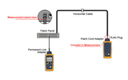
Modular Plug Terminated Links (MPTL) are becoming more widespread in networks but are often new to installers and integrators, making it tricky to avoid common MPTL testing pitfalls.

To help you certify cabling with Modular Plug Terminated Links when installing CCTV, AV equipment and more, here are 3 important considerations.

1. What’s the difference between MPTL and Permanent Link cable installations?

The core difference between a Modular Plug Terminated Link and a typical Permanent Link (PL) is that the MPTL has a female socket (jack) at one end, and a male plug at the other, while the PL is installed with a female socket at each end.

MPTL is used particularly for high-performance cabling infrastructures using cat 6A cable for wireless access points, applications anticipating high-bandwidth demand, and AV equipment and CCTV cameras. The MPTL enables the cable to be plugged directly into a device, so it can be connected to a network without installing an additional outlet, which is useful if the device’s location makes it challenging to install.

The PL has a female socket at each end, so is tested with approved certifier test leads using qualified male RJ45 plugs. Because the MPTL has a male plug at one end, the certifier must be equipped with a female socket to test the plug performance.

When installing, it is also important to note that not all field installed RJ-45 plugs are rated to meet IEC/TIA component specifications, and that you should not exceed 90 meters/328 feet if testing to TIA standards, which require the test to fail if the MPTL exceeds 90m.

2. What equipment is needed to conduct MPTL performance tests?

It is a good idea to check with your cable certifier manufacturer before certifying MPTLs, because if your tester doesn’t have the proper adapters or software, you may receive incorrect test results.
To certify an MPTL is not as straightforward as changing the certifier adapters to give one end the test cord with a plug, and the other end the adapter with the socket. To properly and accurately test an MPTL you need a channel adapter that uses the specific ‘centered’ socket required for the certification of plugs.

Some users will purchase an expensive patch cord test adapter or use a special test cord with the centeredsocket. However, at IDEAL Networks we have developed the best value and most simple solution to the challenges of MPTL. If you are an installer or technician that already owns a LanTEK III cable certifier, all you need to do is download a software update, free, from our website and your LanTEK III cable certifier unit with PL and channel adapters is ready to test MPTLs without any special components.

If you don’t already have one, you can purchase a LanTEK III Channel or PL Adapter, individually through the IDEAL Networks website.

3. What are the MPTL testing standards?

Although MPTL installations are not new, there has never previously been a testing standard in place for this type of configuration. Security, AV and Wi-Fi integrators have used MPTL for years but rarely certified the cable. Because there were no standards in place, cable installers who then tried to create ad-hoc testing configurations often received inconsistent test results.

Due to increased demand for certifying MPTL cable, a comprehensive update to the TIA-568 series, namely the TIA-568.2-D, in 2018 will include MPTL as a recognized cabling topology. Find out more information about the updated standard from the TIA website.

Learn more about Modular Plug Terminated Links (MPTL)

To give you more in-depth information about how to test and install MPTL, we have released an educational White Paper titled “The Rise of Modular Plug Terminated Links (MPTLs)”, which is available to download for free.

It provides in-depth information about how Modular Plug Terminated Links work and the pitfalls to be avoided during installation and testing, as well as looking at Permanent Links, LAN Cable Standardization and Testing Channels.

For more information, visit www.idealnetworks.net.

Article copied from https://www.idealnetworks.net/US/EN/News/3-things-you-should-know-about-testing-MPTL.aspx

Modular Plug Terminated Link (MPTL) Test Limits for DSX-5000 and DSX-8000

Within the draft of the ANSI-TIA568.2-D standard is a new link model named Modular Plug Terminated Link. Previously, the TIA-568-C.2 required that horizontal cable be terminated on a telecommunications outlet to provide flexible access to the user, however in certain limited cases there may be a need to terminate horizontal cables with a plug that is directly plugged into a device.

For most installations, either testing using the Permanent Link model to test from patch panel to faceplate, or to test the whole Channel is the correct approach.  But in those cases where you are installing a far end device, such as an access point or a camera, where it is impractical to install a faceplate, this link model is an option.

The MPTL limits contemplate the use of a Permanent Link adapter, DSX-PLA004 or DSX-PLA804 on one end and a Patch Cord adapter, DSX-PC6ADSX-PC6or DSX-PC5e on the other end. These links are tested against the TIA Permanent Link limits.  The bolded model names are the orderable part numbers for the single patch cord adapters; make sure you order the correct adapter for the jacks and cabling you are using (they are not “backwards compatible for the test limit selection).

The use of a patch cord adapter on the far end that corresponds to the category of cable being tested helps to verify the performance of the field installed plug. If we were to use a channel adapter, per the standard, we would not include the mated NEXT of the plug and jack in the measurement.

To configure the tester to run this test, from the Test Setup screen, select the “Test Limit” and then “More”:


Next we will choose the TIA Limit Group and swipe up to get to the MPTL limits:


Select the required limit.

Remember, the standards suggest running two Category 6A links to access points for new installations.

Author: Jim Davis https://www.flukenetworks.com/knowledge-base/dsx-cableanalyzer-series/modular-plug-terminated-link-mptl-test-limits-dsx-5000-and

What is latest with IEEE 802.11ax

SUMMARY

 image

Key building blocks of 802.11ax. Source: Qualcomm 2016, slide 11. 

IEEE 802.11ax standard is an evolution of 802.11ac. Unlike previous standards that focused mainly on increasing raw data rates, 802.11ax focuses on better efficiency, capacity and performance. This would translate to a 4x improvement in average throughput per user and better user experience. This is true even for dense indoor/outdoor deployments. It’s able to do this due to a number of changes that include higher modulation, more OFDM sub-carriers, and longer OFDM symbol; multiplexing users via MU-MIMO, beamforming and OFDMA; scheduling uplink instead of contention; and mitigating co-channel interference via BSS colour codes.

While 802.11ac used only the 5 GHz band, 802.11ax addresses both 2.4 and 5 GHz bands, thus staying backward compatible and becoming the migration path for both 802.11n and 802.11ac devices.

IEEE 802.11ax is also called High Efficiency WLAN (HEW).

DISCUSSION

  • Why do we need 802.11ax?

    802.11ax overview. Source: Qualcomm 2017.

    IEEE 802.11ac increased raw data rates but left some problems unsolved. Uplink access is mainly based on contention. When there are many devices in a dense network, or multiple access points closely deployed, there can be collisions, backoffs and therefore reduced effective throughput. User experience is affected for all devices.

    The common use cases where this happens is at crowded public hotspots (airports) or event venues (football stadiums). It could also happen in apartment complexes, schools and educational campuses. Also, it’s expected that by 2022 number as many as 50 Wi-Fi devices may be present in a smart home. This growth is mainly due to appliances and gadgets becoming IoT-enabled. IEEE 802.11ax aims to solves these problems from the perspective of overall network capacity utilization, efficiency, performance, user experience and reduced latency.

  • What are the main PHY changes 802.11ax brings compared to earlier 802.11 amendments?
     image

    Key parameters of 802.11ax compared against 802.11ac. Source: National Instruments 2017, table 1. 

    802.11ax supports both 2.4 GHz and 5GHz bands. Therefore it’s backward compatible with both 802.11n and 802.11ac, meaning that legacy clients can also connect to an 802.11ax AP, and vice versa. 802.11ax uses 4x larger FFT by increasing the number of subcarriers but also narrowing the subcarrier spacing, thus preserving channel bandwidth. OFDM symbol duration and cyclic prefix are increased for better performance in outdoor environments. For higher data rate for indoor environments, 1024-QAM and shorter cyclic prefix are introduced.

    While in 802.11ac Wave 2 only 4 simultaneous MU-MIMO streams were possible, this is increased to 8. MU-MIMO in the uplink is introduced while in 802.11ac Wave 2 this was possible only in the downlink. AP will send trigger frames to coordinate uplink MU-MIMO.

    OFDMA is introduced for the first time in Wi-Fi, similar to how it’s done in 4G cellular. With OFDMA, multiple users can be transmitting at the same time, each using its allocated set of OFDM subcarriers. Subcarriers are grouped in Resource Units (RU), which are allocated.

  • What are the main MAC changes 802.11ax brings compared to earlier 802.11 amendments?Since 802.11ax is meant to solve the use case of high density networks, uplink access is scheduled and not based on contention. A new feature named Target Wake Time (TWT) is used to let stations sleep, save power and wake up at scheduled times. AP can thus do scheduling a way that minimizes contention among stations. This can also be seen as a load balancing technique to ease congestion.

    In dense networks, a neighbouring AP can cause cochannel interference. Stations on the overlapping areas will backoff excessively. This is alleviated in 802.11ax by a feature called BSS Color. This helps stations to identify if transmission is from another network and thereby take the right action.

  • For multiplexing users on the uplink path, we have both MU-MIMO and OFDMA. How are they different?
     image

    OFDMA and MU-MIMO complement each other. Source: Qualcomm 2016, slide 18. 

    MU-MIMO increases overall capacity since multiple streams are transmitted at the same time. This is ideal for bandwidth-demanding applications. Transmission to each user is targeted via beamforming. OFDMA does not increase capacity but uses it more efficiently by allocating subcarriers to users based on their needs. With OFDM, a user would occupy all subcarriers for a given time even if that user doesn’t have much to send. With OFDMA, multiple users can be multiplexed at the same time, each using different sets of subcarriers. This implies that OFDMA is suited for low-bandwidth applications. Users will also experience less latency with OFDMA. With OFDMA, multiple users with varying bandwidth needs can be scheduled at the same time.

    Thus, MU-MIMO and OFDMA complement each other. In typical deployments, performance of MU-MIMO in 802.11ac Wave2 was found to depend on distance between AP and clients, channel selection, antenna performance, presence and capability of other clients, etc. Some have noted that MU-MIMO may even result in lower throughput.

  • What are possible implementation challenges for 802.11ax?OFDM subcarrier spacing narrower at 78.125 kHz, which implies that oscillators must have better phase noise performance and RF frontends must have better linearity. Since 1024-QAM is possible, EVM requirements are tighter. Good performance requires tight frequency synchronization and clock offset correction. Stations must also maintain frame timing based on their clocks since their transmissions must be in coordinated precisely as noted in trigger frames.

    Reference

    https://devopedia.org/ieee-802-11ax

Bundling Recommendations for PoE Applications

It is well understood that deploying 30 W and higher remote powering applications, such as Power over Ethernet (PoE) and Power over HDBaseT (POH), over balanced twisted-pair cabling produces a small degree of heat build-up within bundled horizontal cables. This heat build-up does not affect safety, but can affect transmission performance and long-term mechanical reliability. This can vary over differing cable categories and constructions as, for example, cables with larger conductors inherently have less heat build-up due to lower resistance and cables with metallic elements have less heat build-up due to superior heat dissipation properties. Different pathway styles (i.e. conduit versus free air) can also affect heat build-up within cable bundles.

Managing cable bundle size is important to ensure that heat build-up does not exceed the mechanical rating of the cables and that appropriate channel length de-rating is applied to offset additional insertion loss due to increased ambient temperature. While ISO/IEC TR 29125 and TIA TSB-184-A address recommendations for cabling supporting remote powering applications.

The table below depicts recommended bundle sizes horizontal cables supporting a variety of remote powering applications. Note that these bundling recommendations are applicable to cables installed in all pathway types, so they are more conservative than would be specified for cables in free air (i.e. non-conduit) installations.

When in doubt about cable mechanical or heat dissipation capability, installation environment, or remote powering application, a conservative practice is to limit maximum bundle size to 24 cables. With the exception of the few instances noted below, this easy to remember practice addresses the majority of media, environmental, and application scenarios.

Information courtesy of Siemon

A New Acronym To Remember

Information courtesy of Siemon.

Our industry is laden with acronyms from AC (alternating current) to ZWP (zero water peak) and everything in between. The newest acronym making its mark on the structured cabling industry is MPTL. It stands for Modular Plug Terminated Link, which refers to terminating the equipment end of horizontal cable with a modular plug to connect directly into a device vs. terminating at an outlet and connecting the device with a patch cord.

You read about it first in our Standards Informant, but you need to know how the MPTL is used and its impact on the structured cabling industry, as it will affect the way we design a network. Channel implementations with an outlet and patch cord are always recommended for equipment connections because they offer more flexibility, support labeling and administration, and eliminate the need to remove long lengths of abandoned cabling should a device be moved. However, sometimes an alternate configuration is necessary, and this new acronym will help advance intelligent building initiatives as it provides a new means of connection for the growing number of devices that converge on a unified network infrastructure.

Installing a plug (versus an outlet) on the end of a horizontal cable and plugging directly into an end device is not a new concept, as security camera installers have been doing this since IP cameras came into existence in the late 1990s. The problem is that connecting directly to the device with a plug negates the standards definition of a permanent link, which includes the horizontal cable from the patch panel in the Telecommunications Rooms (TR) to the Equipment Outlet (EO), as well as the definition of a channel, which includes the permanent link and the patch cords on both ends.

Because the MPTL is neither a link or a channel, the main issue is testing and certifying the cable segment?  ANSI/BICSI-005 Electronic Safety and Security (ESS) System Design and Implementation Best Practices followed by ANSI/BICSI-007 Information Communication Technology Design and Implementation Practices for Intelligent Buildings and Premises were the first standard documents to accept the MPTL method and referred to it as a “direct connection.” Their solution for testing this cable segment was to override the testing procedure with a “modified permanent link.”  However, since BICSI standards are primarily design and installation guides, they defer to TIA to provide direction on cable types including testing methodology, but TIA had not specifically addressed testing this connection method. Until recently.

A Standards-Compliant Approach

In July 2018, TIA published ANSI/TIA-568.2-D in which Annex F addresses the testing and acceptance of the MPTL termination method for certain limited cases when an equipment outlet and patch cord are not practical – typically in environments where the device is not often moved or rearranged. In the MPTL configuration, the horizontal cable is terminated at a patch panel in the TR and the device end would is terminated to a plug and connected directly to the device, or it is terminated to a Service Concentration Point (SCP) outlet, typically housed in a  zone enclosure, and from there, the cable is terminated to a plug and connected directly to the device.

Image Courtesy of Fluke Networks

To verify the performance of the final plug connection at the far end, the ANSI/TIA-568.2-D standard also includes a new test procedure that includes the final plug connection . It does this using a permanent link adapter at the TR end and a patch cord adapter at the far end where the cable terminated to the plug. The test figure shows the testing configuration (courtesy of Fluke Networks). It’s important to note that the tester you use must have the proper adapters and software to accurately test this MPTL scenario.